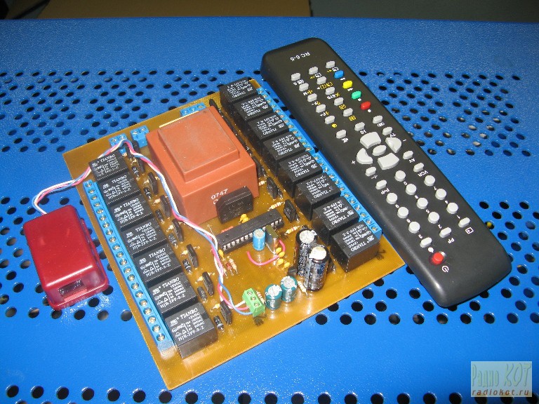
15-channel control system electrical
As they say, laziness - the engine of progress. Perhaps, therefore, all the more common remote control of appliances, household appliances and lighting. Of the "Smart House" is widely prevalent in the West are just starting to emerge from us. The prices of most basic remote control lighting, blinds, garage doors, etc. off
scale for the level 20000 ... 50000 €.Not every resident of the
countries of the former USSR could afford to install such a "smart"
complex. Next set of "Sapphire" to control the chandelier in most cases does not reach. And
I would like to use our Slavic wit to complete, the more hands that
grow just from where polozheno.Razrabotano several options for control
module electrical differing in both functionality and the number of
outputs for connecting loads. This paper presents the most "advanced" version with the ability to control and settings from your computer.

Key features of the developed device:
· 15 outputs for connection of loads;
· Remote management and configuration using any remote control that works via RC-5;
· Storing 21 commands from the remote control during the study;
·
Programmable switching outputs from the various remote controls (for
example, control of outputs 1 ... 10 from a single remote control, and
control of outputs 11 ... 15, and service functions of the remote
control with other system address), and each of the remote controls only
"their" outputs;
·
Each of the outputs can be operated in trigger mode (changing load
status incl. / Off. Once you push the button) and in the time of
activity (the load is switched on for the time set in the menu for the
channel from 1 to 100 seconds. in increments of 0.1 seconds.)
·
Switch off the auto-off timer load after a specified time in the
absence of accepted commands from the remote control or keyboard;
· The range is set in the menu of the automatic shutdown of loads from 1 minute to 999 minutes in 1 minute;
· 1 digital input for connecting a chain of photodetectors;
· 1 analog input for a 17-keyboard command or local light switches;
· Function software "bouncing" on the keyboard and the delay performance of duplicating remote control commands.
· The ability to connect up to 30 types of photodetectors ILMS 5360 in a parallel-wire line;
·
The ability to connect a large number of limit switches or a
full-featured keyboard units, located in different areas within the
existing two-wire line 220.;
· Switch off the menu sound with beeper to inform the inclusion of loads incorrectly received the commands and the like;
·
The ability to connect on a two-wire line to the 100 12-volt beeper
with a built-in generator and the ability to arrange them in separate
rooms;
·
Preservation of all the settings and status of the loads in
non-volatile memory controller and restore them after the power to the
unit;
·
Be switched off via the menu system function "antipovtora clicks" that
did not allow the load to "pull" (ie periodically switched on and off)
by holding down the key or remote control keyboard;
·
Reset the "default" from the system menu, and all outputs are set to
trigger mode, auto-off time is set to 12:00, turn on the sound;
·
Control of all functions of the device from a PC via the interface
RS232 (via COM port or adapter USB-COM) using the program "Sokol
DRCS-15M terminal";
·
Display in the main window "Sokol DRCS-15M terminal" output status (on /
off) by changing the color of the controls and labels;
· Read, write, and modify all device settings via the control program "Sokol DRCS-15M terminal";
•
Automatic shutdown keyboard when entering the menu system and its
subsequent activation upon completion of the settings and exit from the
menu, to eliminate false data entry.
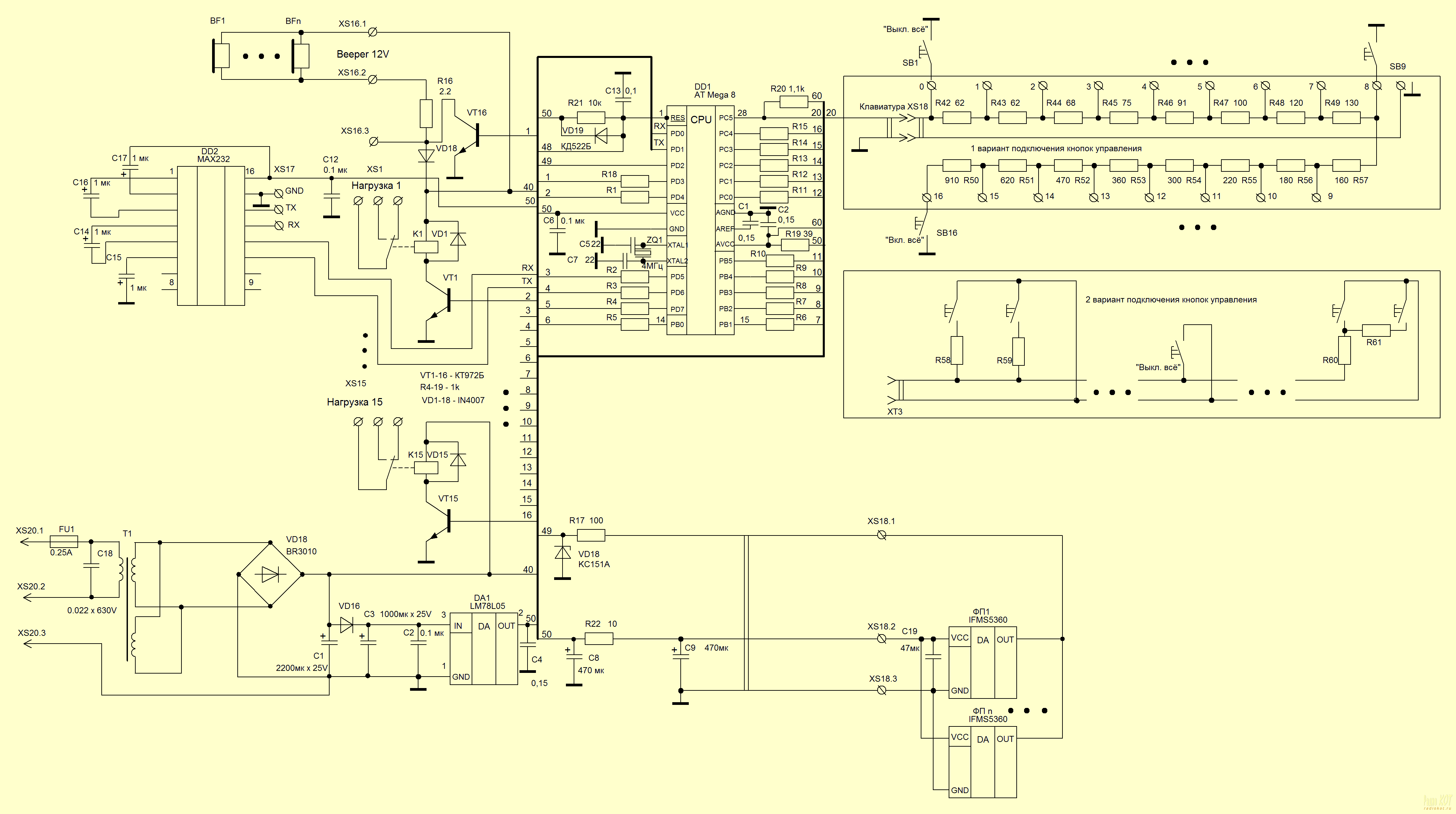
Description of the electrical circuit diagram and wiring your device:
The
basis of the device is a microprocessor with a "hard-wired" control
program that takes care of handling all incoming from sensors and
switches information and make the necessary calculations. The control microcontroller can be like "old man" AT Mega8, any letter index and newer AT Mega88 or AT Mega168. Firmware
for all types of microcontrollers are contained in the archive, which
you can download from the link at the end of the article.


Drawings PCB LAY format can be downloaded from the links at the bottom. There's also an archive of cards with pictures in BMP, including a picture of the elements. I note that one of the variants of the PCB is used and developed for the mass production of modules. Therefore,
not only contains the charge of the central module SOKOL DRCS-15M, but
the board of the photodetector and the keyboard ...
To
connect the device to a computer in the scheme provides an interface
RS232 (COM-port) and driver-level converter - MAX232N (DD2). Although you can use USB-UART converter, such as chips FT232, or even a "string" of a mobile phone based on PL2303. The
truth in this case will have to develop their own printed circuit
board, but it is possible to directly connect the device to a personal
computer via USB. But for the
USB connection, you can also use USB-COM converter, using a bunch of
those same MAX232N + MAX232N or their analogues.
The
relay can be any, calculated on the supply voltage of 12 V. and proper
amperage in the secondary circuit.Denominations other circuit elements
with the exception of resistors R20, R42 - R57, form a voltage divider
keyboard is not critical. Said resistance should be adjusted to within ± 5%. As
can be seen from the above, the microcontroller determines the number
of the key pressed on the level applied to the input voltage PS5 by a
software conversion voltage code of the pressed button. If
several buttons to be pressed at the same time then, as seen from the
scheme of the keyboard key has higher priority to lower numbered
command. Appointment of manual control buttons as follows:
"Disable all" - turn off all active load
1 ... 15 - Management of the respective outputs.
"Include all" - to include all active load
VD18
zener serves to protect the microprocessor against transients which may
occur in the connecting wires at their considerable length.
A multitude of connectivity options button manual control. Figure 1 shows two of them.
The first is to produce a separate fee keypad located on it a chain of resistors and screw terminals. PCB pattern just beside the main unit and the photodetector includes a keyboard and a fee. In
this case, the buttons are connected to the corresponding pins and
clips can be separated by a considerable distance from the base unit. Herewith, buttons parallel connection, for example, to control lighting of the various parts of the corridor, etc. In
this case it is advisable to use the existing electrical wiring and
state switches, but you first need to avoid getting into the mains
supply to the circuit elements and key switches replaced by push switch
position (you can just install the switch inside the recoil spring).
The
second option involves the location of the resistors directly into the
body of each switch or its associated junction box, while it is also
possible parallel connection of the control buttons, but only when the
body of each resistor in the appropriate rating. In this case, charge the keyboard can not be made.
To
calculate the voltage divider resistor values for both variants of
the article has been placed at the end of a spreadsheet in MS Excel. In the green box enter the resistor R20 in ohms. Then
in the blue column will be calculated resistor values for the second
option schemes enable the keypad buttons, and yellow - for the first
one.
In
the event that the device will be used for centralized control of
lighting, both in the author's version, in a newly built house (or
renovated) it is advisable to install the module to a suitable
electrical shield. In this
case, all the wires from the load (lamps) and wall switches limited to
the remote control unit and connected thereto in accordance with the
diagram. When laying new
wires need to take into account that for the connection of integrated
photodetectors is desirable to use a twisted pair category 5E, with the
use of two pairs of the four available. Connecting
photodetectors should be such as to reduce the likelihood of
penetration is minimal interference pulse at the input circuit. EXAMPLE twisted pair shown in Table 1. Free pairs can be used for their intended purpose (LAN 100Mb / s., Phone, etc.). The
cable shield, however, as the body of the distribution panel, to reduce
interference with the device must be connected to ground. Common wire circuit must also be grounded. The
case of the distribution of the electrical device must be connected to
ground, and according to the regulations of Design and Operation of
electrical installations. Available
free pairs you can use to connect the beeper and the control buttons
(an example of this connection is shown in Table 1).Such a connection is
quite convenient, as the beeper and a photo you can place a
constructive one package and install, for example, on the ceiling of the
room. Using a free pair to
connect the control buttons (the second option for the connection)
allows to reduce the financial cost of the additional wire, and raise
immunity device. Handling
routine keystrokes, however, and so has sufficient noise immunity, due
to the use of algorithms for key pressed with the prediction result and
error correction.

Operation of the module and the first inclusion:
At
power up the microprocessor adjusts the input-output ports, and
initializes the embedded devices in accordance with the firmware, and
then check if you pressed "disable all" on your keyboard. If pressing the controller will be locked gives two long beeps and pass away in a learning mode remote control commands. Otherwise
hear one long (500 msec.) And three short (100 ms). Beeps and the unit
enters the operating mode in which the load control is performed. Note,
however, that when you first turn on the microprocessor memory does not
contain a control command codes, and requires a "learning" device. If
you do not, then when you click on any buttons or remote control keypad
will sound an error tone (one beep and the average duration of three
short), indicating the reception of an incorrect command. After programming the remote control commands to the system menu to reset the default settings. How to do it is written on.If the reset does not produce that normal operation is not guaranteed.
After
clicking on any of the buttons on the remote control controller
compares the received code with the codes that are stored in memory, and
if any matches performs the appropriate command. If
no match is supplied (when the sound), the corresponding error signal,
one signal average duration (300 ms.) And three short (100 ms.). When a command designating a load beep will sound. When receiving commands include all or disable all will sound two short (50 ms). Beeps.
In
the absence of remote control commands or keyboard controls for a
specified time (see "Installation of the automatic load-shedding in the
absence of signal control module"), all active at the moment the load is
disconnected. In this module will give six long beeps, meaning the timer is activated.
If
you have enabled antipovtora pressing the corresponding load is
switched each time you press the button on the remote control or keypad
only once. To re-switch must be released, and then press the corresponding key. If
the antipovtora clicks off, and the output works in trigger mode, when
you hold down the switch will be switched to the opposite state with a
frequency of about 3 Hz. If the output is in the time of activity, the timing in this case, only after the start button is released.
Management Program "Sokol DRCS-15M terminal":
To
manage all functions of the device, a special management program, which
allows not only to control the output, but also to all the settings,
including the programming of the remote control commands.

The appearance of the main window is shown in the figure above. When you run the program scans your computer's ports, searching the available COM-ports. Found ports are displayed in the "Select COM-port." If
the ports are not detected, instead of a list of ports will display the
message "No port" and the button "Connect to device" is not available. Unless the connection to the apparatus control buttons remain inactive. To
connect the device to select from the available COM-ports the one to
which the device is attached, set the desired baud rate (the current
version of controller firmware - 19200.), And then check the "Connecting
to the device." For any
change of status outputs of the device buttons will change their color
(green - the output on / red - off) and an inscription indicating an
event that happens when you press the button.
The "About ..." does not need to be explained.
When you click on the "Advanced ..." is displayed the device settings.

The "Read" is designed to read the current settings of the device. The "Record" - record your entries in the device memory. The
"Import settings from file" and "Export settings to file" are,
accordingly, to save the device settings in the configuration file (*.
Drcs) and reading the previously saved settings for recording to the
device from a previously saved file.
Provided reset device "default" is not only on the remote control, but also through the control program. For a "foolproof" reset procedure is intentionally complicated. Originally button "Reset Settings" is not active. In order that would enable it to establish a tick in the box "Allow reset." After this reset button turns red and reset the unit will be allowed. On
the resolution of the reset management program to provide additional
information window (see figure below), after the close of which, by
pressing the "OK" button, maybe this is the reset done.

In the future when you press the "red button" message is displayed on the result of the operation: turned or not :).


For
normal operation of the program must be installed on a computer package
Microsoft. NET Framework, which you can download from Microsoft. The
efficiency of the program tested in the operating systems Windows XP
(SP1, SP2, SP3), Windows Vista, Windows 7 processor-based AMD, Intel x64
and x86.
Education remote commands:
How to get into training mode described above. In this mode, the device waits for the buttons on the remote control, the corresponding executable commands.
The order of pressing the buttons on the remote control for the initial programming of the module is defined as follows:
1. - Switch off all loads / time setting automatic shut-off when you are in the menu system;
2. - Enable / disable loading 1;
3. - Turn on / off load 2;
.................................................. ...........
16. - Turn on / off load 15;
17. - To include all loads operating in trigger mode / output mode setting when you are in the menu system;
18. - Input to the system menu;
19. - Enable / disable the sound (beep) when you are in the menu system;
20. - Reset the default settings when you are in the menu system.
21. - Enable / disable function antipovtora while in the menu system.
After
clicking on each of the buttons microprocessor is stored in nonvolatile
memory code corresponding to the key pressed, and provides a short
beep. When you click on the
code that was already stored in memory (the button was pressed or
previously held down at the moment), the unit makes three short beeps,
indicating an error. After
the procedure, remembering sound two long and three short beeps, and the
unit enters the operating mode in which the load management.
The system menu and settings:
To enter the menu system module, press the corresponding key on the remote control (see "learning remote control commands"). Call up the menu with the keyboard purposely does not provide. Enter the menu with three beeps mean duration. At
the same time while navigating through the menus, each received command
is accompanied by a corresponding audio signal, no matter whether the
sound. That is, while the user is in the menu, the sound will be fed device regardless of the setting.
The
following infusion by pressing the appropriate buttons on the remote
control after entering the system menu (see "learning remote control
commands"):
1. Enable / disable the sound (beep). In
addition, each press of the remote control is number 19, or inclusion,
or mute.If the user press a button to silence the buzzer, in support of
this unit will signal the average duration of two, with a real mute will
only be executed after the menu. If the user has turned on the sound, the module will respond with one signal average duration (200ms.). The sound in this case will be included and after the exit from the menu system.
2. Setting automatic load-shedding in the absence of control signals module. When
you click on "disable all» (№ 1 on the remote) will emit a single long
beep and I will wait three digits (0 ... 9) on the remote control keys,
confirming each received a figure with a short beep. At the end of time I will be served one long and two short beeps. Please
keep in mind that the entry is made directly digits numeric keys keypad
(code range in the RC-5 from 00000 to "0" to 01001 for "9"), and not
the button corresponds to loads (№ 1 ... 10). When
pressed, the remote control is not true any audio signal is not
supplied, the module will expect to receive digits, confirming a single
beep only numeric values. If
the value of the time was entered incorrectly, you must either disable
the module from the power source to the input end of three digits, or
complete the entry and after the beeps mean the end of all digits are
entered, re-enter this submenu and enter the correct value. If you set the auto-off to zero (a combination of "000"), the timer is disabled and automatic shutdown loads will not occur. Increments of time is one minute (999 min. At "999").
3. Setting the active state for each of the control channels. When
you click on "enable all» (№ 17 on the remote control), the device will
emit two long beeps and waits for the input of three digits (0 ... 9)
on the remote control keys, confirming each received a figure with a
short beep. After entering
the active time for the first channel will be served an additional one
long beep and the module will wait for input values for the second
control channel and so on, until all 15 control channels are programmed
in a similar manner. After entering the last digit combinations in addition to a long sound signal unit will have two long and three short. Increments of time in this case is 0.1 seconds (99.9 seconds. At "999"). If you enter a combination of "000" for which either of the channels, the current channel will operate in trigger mode. In the case of input error requires repeated action as described above.
4. Reset to default. Pressing
the number 20 on the remote control unit will signal the two average
duration (200 ms.) And one long (500 msec.), All outputs are in the
trigger mode, the automatic disconnection is set to 12 hours and unmutes
function antipovtora taps.
5. Enable / Disable the antipovtora taps. In addition, each press of the remote control number is 21 or inclusion or disable antipovtora. If
the user is pressing the button has turned off antipovtora, in support
of this device will beep once the average duration (200 ms.) And one
long beep (500 ms.). If the user has activated antipovtora, the module will respond with two beeps is the average duration and a long one.
When in the menu system, press of the button number 18 on the remote control works exit. The yield of sub similarly impossible. Turn
off the power module or finish entering data in the current sub-menu
and then exit from the main menu, the respective command.
Recommendations for the choice of the remote control:
When selecting the remote control, be aware that it is imperative his work on the protocol RC-5. It is necessary also that the number of generated code chip is not less than 21. It should be remembered that the presence of, for example, 40 control keys can not guarantee. that the remote can supply 40 different teams. Many
modern buttons on the remote control and duplicated though and have a
different signature panel are electrically connected in parallel (for
example, "-/--" and "<=" in remote RC6).
 It
is advisable to use the remote with a non-zero-address system, if, of
course, readers will not want to repeat the construction to operate the
device simultaneously with the TV or trust your neighbor's house, which
is changing channels will "play" with your lighting.
It
is advisable to use the remote with a non-zero-address system, if, of
course, readers will not want to repeat the construction to operate the
device simultaneously with the TV or trust your neighbor's house, which
is changing channels will "play" with your lighting.
For sale is a set of universal remote control, which you can select addresses the managed device. For
example, a series of panels RC6-2 ... RC6-5, is widely used in
conjunction with a TV «HORIZONT» sixth generation, change the address of
the device from "0" to "5" when pressed together with control buttons
keys «VCR». This allows us to
use the remote in a series of RC6-2 ... RC6-5 with 42 buttons and
forming 40 teams of management as to control the TV and the device
described, except for a mutual influence.
 The
ideal option is the subsequent conversion of the remote control, which
allows you to change the address or switch to betray him.
The
ideal option is the subsequent conversion of the remote control, which
allows you to change the address or switch to betray him.
As
the programming of the switching outputs of the various remote controls
(for example, control of outputs 1 ... 10 from one remote control, and
control of outputs 11 ... 15, and service functions of the remote
control with other system address), and each of the remote controls only
"their" outputs, this possibility is also not to be sniffed
at.Alternatively you can use a remote control with a small number of
buttons, but a switchable system address (usually for the purpose of
import into the remote control by pressing the key "Shift"). If there is no switch you can install it yourself.
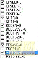
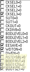
Programming the microprocessor:
Firmware for both types of processors can be downloaded in the archive link at the bottom of the article.
How
to be programmed Fuse-bits controller for AT Mega88 microcontroller and
AT Mega168 among CodeVisionAVR shown on the right, and to the
microcontroller AT Mega8, AT Mega8A, AT Mega8L - left.
Tidak ada komentar:
Posting Komentar