Voltmeter, ammeter, power meter, with display Nokia511
Diagram:

Details: Nokia 5110 display controller-based PCD8544, MK ATmega8 any letter, in DIP and TQFP performance . And OU Lm 328 or Lm 2,904.
- dual-band voltage meter, the total measuring range from 0 to 100 V .
① from 0.00 to 9.99 V . voltage measurement resolution of 0.01 V ,② from 10.0 to 100.0 V voltage measurement resolution of 0.1 V .
- ammeter 0.00 to 10.00A 0.01A current measurement resolution.
- Protection of trigger on excess consumption amps
- voltmeter number 2 and number 3 with a measuring range from 0 to 30 V .
- power meter,
- range from 0.00 to 999.99 Watt , step display measuring 0.01 watts.
- mapping of internal resistance connected load in the SM
- Thermometer accuracy of 0.1 ° C
- hardware PWM (PWM) IC, the frequency of 62.5 kHz,
duty cycle - Shima is displayed in the main screen% basis, from 0 to 100%
During operation, the control buttons, KH1, KH2, NH3 ;KH2 makes a choice (set cursor) to the PWM control or setting the threshold drawdown protection ammeterbutton KN1, NH3 perform the function of reducing or increasing, protection threshold amps or PWM values.(Reset protection will ammeter is made by pressing any key KN1, NH2, NH3 )
Setting up the scheme after assembly (first start).
Setting the voltmeter: start with the first sub-band is input to the "0-100 V " any DC voltage to 9.98 V,and comparing with the test voltmeter, set up trimmer R -1 equally visible readings,and behave similarly to the second subband,provide the input to "0-100 V " voltage of 10.1 V and comparing with the test voltmeterset up trimmer R -2 same voltage reading.Voltmeters number 2 and number 3 are adjusted resistor R -4, R -5.Change the range of the ammeter (up to 20A and 30A, the default is set to 10A ) can be so set the jumper on the total supply, 19 foot (port RV5) to include a scheme to check visually the installation of security resulting range, if the range is the one that is required to remove the jumper if not, repeat the action.(NOTE! Choice of a new range of the ammeter in the working scheme would entail trimming resistor feedback circuit ammeter and the subsequent adjustment of the resistor R -3 )R -3 adjustment of the ammeter.An example of a possible connection schemes and relay voltampervattmetra, in the laboratory power supply.
FUSE . MK RS clocked from the internal oscillator at a frequency of 8MHz.

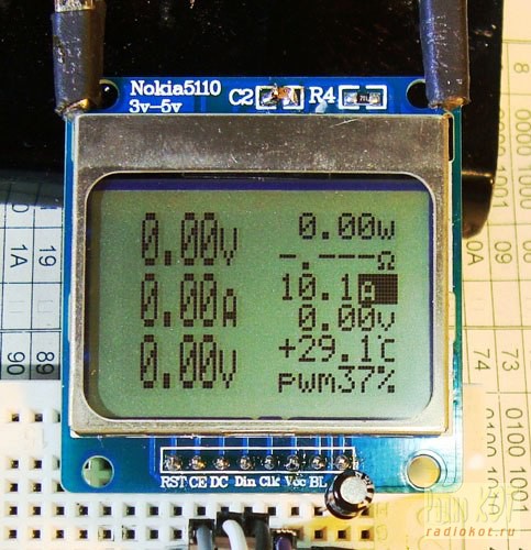
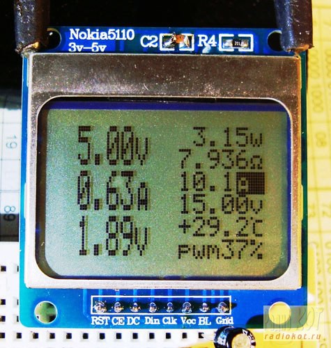
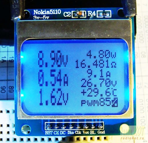
Photos, displaying information on the display.

A few words about the work of the PWM output in this scheme ...
To the question, why do we need it? I now have no answer ....))) In this scheme, it is connected to the highlight indicator, a little video how it works (duration 2min.12sek.)
In the main screen when the cursor is positioned on the symbol % duty cycle regulated buttons KN1 , NH3.

PS power supply of the scheme.
In my version, 5V power supply. Here and there displeychike which Nokia5110 written 3 - 5 volts.
In practice, this is normal, but :)) reminded me of some long-standing association, about 1 watt Chinese ... 1 Chinese amps ....
In general, check the work of the scheme, with the help of his LBE.
The result, in the range of 2.6 to 5 volts, the circuit produces a measuring and operating normally. So here it is, comrades users, the choice is left to you, proven 3.3 volts, or do not doubt anything, and we use the usual 5 volts ....
That is really very good article. I am glad to know. Thanks for sharing !
BalasHapusTimber playground equipment
School playground equipment suppliers
Playground equipment leeds
siip
BalasHapusbuenas noches como adquirir el .HEX de este voltimetro amperimetro esoy interesado gracias
BalasHapus